
Control a Gottlieb System 80
with LINUX
LInux
for SYstem 80
Control a Gottlieb System 80
with
LINUX
Version 2.3, 05.01.2008
I started the project because I wanted to combine my three hobbies:
- design of electronic circuits
- programming with C, especially under LINUX.
- repairing and (of course ;-:) playing with Gottlieb pin's, especially Gottlieb System 80 'Star Series'
- Any type of LINUX distribution (Debian 4.0 Etch in my case), with software development installed,
( Gnu-C compiler, ..)
- For documentation and layout TARGET 3001! V11. There is a free version available
at
http://www.pcbpool.de/ , as long as you send the layouts to pcb-pool.
- a Gottlieb System80 pinball machine, the MPU will be replaced by LISY80.
- An old Intel PC, all you need is a working USB Interface, my development system
is based on a 300 MHz HP desktop and a 500 MByte hard disk.
- lot of electronic stuff (TTL IC's, resistor, ...)
special stuff:
-IO-Warrior 40 from
Code Mercenaries
for the USB and I2C Interfaces and as well for the switch matrix
- PIC 16F872 for controlling the displays.
- PCF8574 for die control some of the coils.
The link to the PC hardware is done by the USB interface. For this I use the IO-Warrior 40 (data sheet ).
There is a IO library for Linux as well as for Windows available. For details visit
Code Mercenaries.
IO-Warrior could handle a 8*8 switch matrix, so this fits perfect in a pinball design.
First tests with IO-Warrior and USB proved that the USB bus ( Version 1.1) is to slow to handle
the refresh cycles needed for System 80 and System 80A. So I designed a refresh circuit based
on the PIC16F872
(data sheet) and wrote another C program to control the display refresh.
The PIC is controlled by the IO Warrior over I2C Bus.
Because mostly all of the IO pins of IO-Warriors are covered, I had to add an I/O-Extender PCF8474 (data sheet).
Der PCF8574 extends the IO with 8-Ports, controlled via I2C bus.
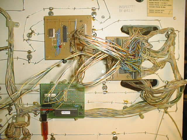
Below a picture of my very first version. At the left top you see the PIC circuit for the display refresh.
At the right there is a special 'driver board', at the bottom left you could see the original IO-Warrior 'starter kit' circuit.
With this it was possible to control all the displays.
.
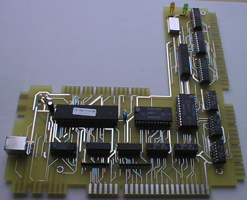
Based on version 1, I designed my own circuit.
For this one I used a lot of PCF8574 and standard connectors.
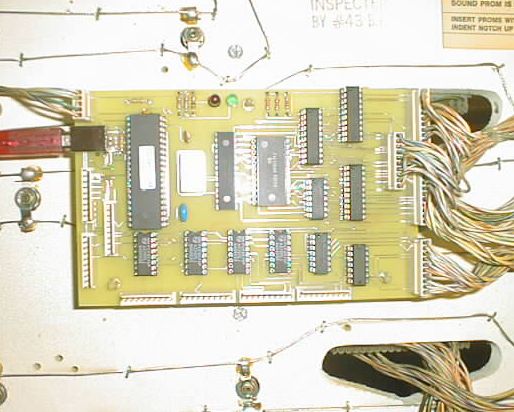
This one use only one additional PCF8574. The edge connectors are compatible
with the original Gottlieb ones. It is now possible to easily swap the Gottlieb MPU
with this circuit.
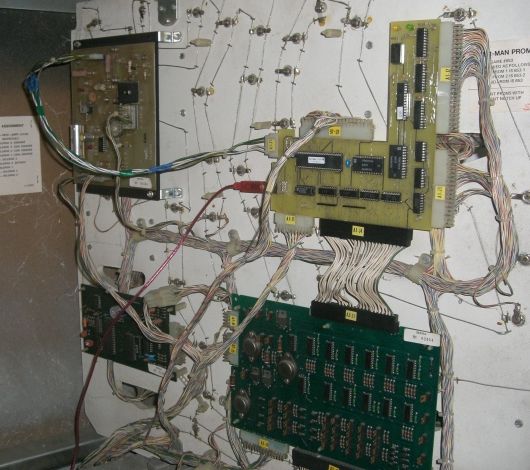
Picture of the backbox from my Gottlieb Spiderman. The original MPU is exchanged
by LISY80. The red USB cable in the middle connects LISY80 with the PC (external for now).

Spiderman with LISY80. You could see the writing 'LISY80' at player
one, and the version number (v. 0 05) at the status display.
Follow the link to see a short video, demonstrating LISY80 (caution, file size is more then 8 MByte ! ): Spiderman.AVI
Video shows the flow of this short testprogam: Spiderman.c
what does the program do?
- initialize the hardware. You could hear completion of this, by stooping the noise after switching on the pin
- waiting that someone press the 'replay' button
- if replay is pressed, display 1 shows '00', display 2 to 4 are erased and the status display shows '01'
- every following pressed switch counts 10 points for player one.
- if the ball went in one the 3 holes, it is ejected immediately.
- if the ball goes 'off' ( OUTHOLE switch is pressed), the program ends and Game Over lamp is activated.
At the upper left of the playfield I placed the display of the controlling PC. If you do a closer inspection
you could see that when the ball hits a switch, the program reacts with doing printing out
some debug stuff.
- 'Ball Save'
- possibility to type in someones 'initials' in case of a new highscore
- automatically send the score to a central PC, useful e.g. for tournaments
- and lot more ....
mail: ralf (at) flipperkeller.de